LEGION XXIV CATAPULTA PAGE
LEGION XXIV's CATAPULTA AND ONAGER "ENGINES OF TERROR"
Last updated July 08, 2008

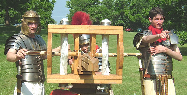
The last sight enemies of Rome may see when confronted by Legion XXIV's Engine of Terror.

Centurion Hagarius hasn't heard of Legion XXIV's Engines of Terror!
The term catapult comes from the Greek word "Katapeltes" "shield piecer" (kata = through, pelta = small shield"). A Roman Legion probably employed 10 of the larger stone throwing "Ballista" engines, as above, one for each Cohort, while one smaller "Catapulta" arrow bolt shooter would be assigned to each of the Legion's 59 Centuries. One Contubernium (squad of eight men) of each Century would be assigned responsibility for the emplacement and maintenance of the catapulta engine. The so-called "Scorpion" catapulta was a smaller two-man portable torsion-powered arrow shooter. It is believed that Auxiliary units did not have catapultae assigned to them.
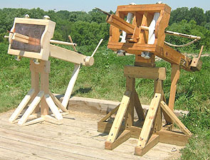

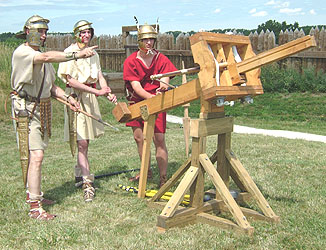
The two Legion XXIV catapulta emplaced at the Little Battery position at Fort Meigs, overlooking the Maumee River in Perrysburg, Ohio, in June 2006. The "Canuck's Revenge" engine, on the left, was assembled by Joe and Thomas Perz of Amherstburg, Ontario. It features a face-plate bearing icons and the Legion's designation and is modeled on the Commander's "Engine of Terror" on the right. Both are capable of casting light weight arrows 300+ feet and heavier arrow bolts some 200 feet. Both machines are of the so-called "Euthytone" (Greek for "stretched-straight") design, where the torsion skeins and stanchions are in a straight line side to side within the head-frames. Legion XXIV probably has the distinction of being the only Roman military reenactment unit capable of fielding up to three artillery pieces: these two catapulta and the "Wojick" onager, stationed in Massachusetts.
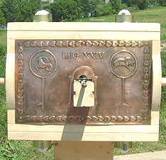
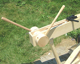
The face plate on the Perz's "Canuck's Revenge" is shown with an arrow protruding through the plate's orifice. The plate is nicely and accurately decorated with embossed icons, a border design and the Legion's designation. The historically correct windlass (carchesium) and "claw" trigger of the "Revenge" engine are shown at the right.
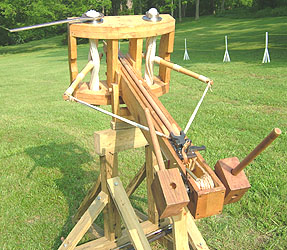
The Ballista-Catapulta was powered by two horizontal cross-bow like arms, which were inserted into two vertical and tightly wound "skein" springs composed of leather or sinew or hemp or combination of these materials contained in a rectangular frame structure making up the head or principle part of the weapon. The arms were drawn rearward to further twist the skeins and thus gain the torsion power to cast a projectile. There is no evidence that the Romans ever used metal springs in their torsion powered weapons. Legion XXIV's two Catapulta Engines are of the "Euthytone" (stretched-straight) design, where the skeins and stanchions are in a straight line side to side within the head-frame. This arrangement limits the forward travel motion of the arms when discharged and is typical of smaller torsion-powered machines. The somewhat more efficient and generally larger "Palintone" (stretched-back) type of ballistae, where the skeins and vertical stanchions are staggered within the head-frame, permits the power-arms (bracchium) to travel in a greater arc during discharge, yielding more power and range. See our Ballista Page for photos and details of a large "Palintone" style "stone-throwing" ballista.
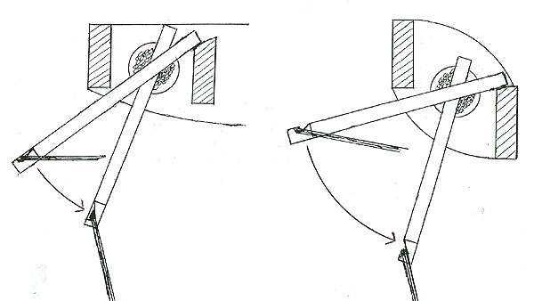
EUTHYTONE "Stretched-Straight" PALINTONE "Stretched-Back"
Note how the staggered stanchions of the Palintone head-frame allows for a greater angle of arm pull-back from the "at rest" position and then more distance of forward travel when discharged. The Euthytone arrangement is generally found on the smaller arrow/bolt shooting "Scorpion" catapulta "shield-piercer" machines. Also note that the heals of the arms impact upon the inner stanchions when discharged and remain there when "at-rest" and do not contact the outer stanchions at any time. The outer stanchions are generally notched on the rear edges to allow clearance for the arms to travel a little further upon discharge. Diagram by George Metz - Legion XXIV
The Onager was developed as a simpler version of the Catapulta-Ballista. It has only one large skein placed horizontally within the frame with a large vertical arm, usually with a sling attached at its upper end. Thus only one skein had to be maintained, as opposed to the two skeins of a catapulta engine. The term "Onager" comes from the Latin word for "wildass", referring to the "kicking" or "rearing-up" action of the machine when it is discharged. The Onager is the usual type of device generally associated with the term "Catapult".

Legion XXIV's "Engines of Terror" at Roman Days Northeast, in Woodstock CT, on May 15, 2004. At Left is the "Scorpion" arrow-shooter Catapulta on its original base, flanked by our stone (baseball) throwing Onager. Both have a range of about 200 feet. Andy "Roman Dude" Volpe, of the Higgins Armory Museum, is manning the Scorpion, while Marcus Quintius Clavus (Quinton Johanson) of Leg-XXIV crews the Onager. The Onager was built by the Wojick brothers (Fred / Flavius & Greg / Gallus) of Legion XXIV and is still undergoing operational trials - Then look-Out! Legion XXIV may be the only historically accurate Roman reenactment unit in the United States fielding two artillery pieces.
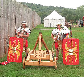
The Wojick brothers, Flavius Octavius Servius and Gallus Octavius Oppius, with their Onager ballista, stand ready to defend the palisades from the enemies of Rome at Fort #4 in Charlestown, NH on September 24-25, 2005
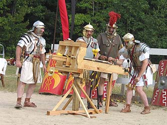

Legion XXIV's "Scorpion of Terror" on its original base, being cocked, at left, and then being discharged, at right, during Roman Market Days 2003 in Hollis, Maine.
The Legion XXIV Catapulta Engine was constructed by Kurt Suleski (Darius Architectus), the builder of the larger "Palintone" Ballista described on our BALLISTA PAGE. It is a smaller and tamer version intended to cast light-weight plastic tube ammunition with a tennis ball head, for use during SCA sanctioned battle events, but is capable of, and has been used with "live-round" iron tipped arrow-bolts and Dura-Europos style arrow-darts. The machine is about six feet to nine feet long, depending on the extension of the slider rail. It is over four feet wide and more than five feet high, over the torsion head and is a reasonably accurate replica of those used by the Roman Legions.
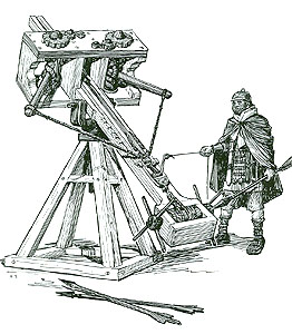

Ballista "Ready" and "Onager in Action" from "Weapons" by Edwin Tunis, 1954. Note that the onager's arm is still in motion toward the stop-frame, as the projectile is released from the sling pocket after the sling ring has slipped off the prong at the top of the arm. Also note the winter style dress on the legionary at the ballista, and the tie-downs at the rear of the onager to restrain its kicking action upon discharge.
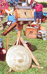
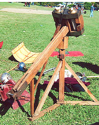
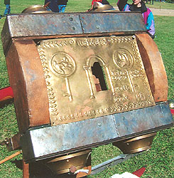
A small two-man portable "euthytone" type "scorpion" arrow shooter of Dan Peterson's Legion XIV. Note the iron reinforced head-frame and the decorated brass face-plate with the aperture through which the arrow-bolt is discharged. One of these weapons was assigned to a Contubernium "squad" in each Century of a Legion.
Both the Ballista and Onager were rather high-maintenance devices and were vulnerable to having their leather or sinew or hemp skeins get wet or even damp, which would cause them to slacken and lose tension, rendering the engine useless. Also, both types of machines required a skilled crew to tighten the skeins and keep the weapon adjusted and ready for deployment. This was difficult enough in peaceful conditions, not to mention during the heat of battle, so the death or injury of a critical crew member could compromise the effectiveness of the weapon.
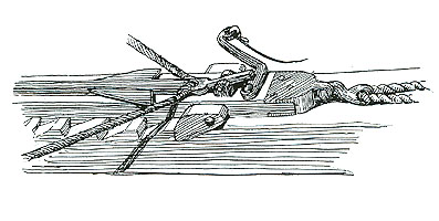
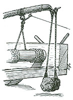
Catapulta / Ballista trigger detail showing cocking pawl, and at right, detail of an onager loaded and ready for discharge from "Weapons" by Edwin Tunis, 1954. Note the onager's trigger and cocking windlass, and the projectile hanging in the sling pocket and the release ring of the sling hung over the arm prong.
8888888888888888888888888888888888888888888888888888888888888888888888888888
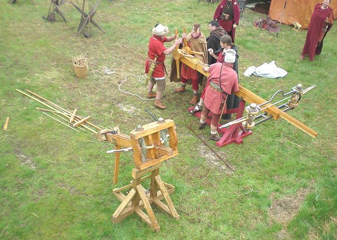
ABOVE and BELOW - Views of Legion XXIV's "Engine of Terror", on the left, alongside a later 2nd Century AD design catapulta of Legion VI stationed in California. The "engines" are being set-up in preparation for a "shoot-off" during the "Lafe-43AD" Event, in Lafe, Arkansas, on March 7, 2008. Both weapons proved to be worthy competitors, with the Leg-VI machine being somewhat longer in range by about 30 yards. However, Legion XXIV's older, more compact and experienced "Engine of Terror" had a much higher "rate-of-fire" of about three discharges per minute, while the Leg-VI machine, in its current configuration, was somewhat clumsy to set-up and unwieldy to aim and discharge. Legion-VI's Engine gained some "movie credits" when it was featured in an episode of Sergeant "Gunny" Ermey's "Mail-Call" program on the History Channel during 2006. legxxiv-057,058
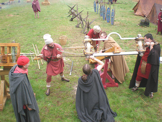
Note the differences between the two "engines" in design and construction. The Leg-XXIV machine represents a large arrow-dart thrower typical of the Early Empire into the 1st Century AD Period, while the later design of Legion VI's catapulta came into use during the 2nd Century AD. The later 2nd Century AD design had the advantage of a longer arc of arm travel of about 80 degrees during discharge, which along with its longer sling length, yielded a greater effective range, as opposed to the shorter sling length and approximate 45 degrees of arm travel on the earlier, but more compact design Legion XXIV weapon.
88888888888888888888888888888888888888888888888888888888888888888888888888
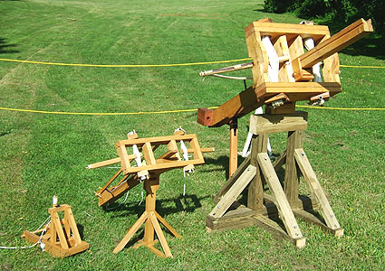
Legion XXIV's "Terror Weapon" on its new historically accurate and more stable base, with two much smaller contenders at Roman Days 2004. At left, is a small toy-like onager with a sling that casts golf balls a surprising 25 feet! In the middle is a rather wimpy "scorpion" arrow shooter built from a commercial kit. It needs larger skeins with more bulk and greater tension to be a serious threat. However, both of these smaller machines are not that easy to construct and are a credit to their builders.

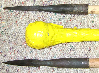

Barbarians, Pesky Celts and other Enemies of Rome should take due notice, that the Commander has made some serious "live round" ammunition in the form of two one-inch diameter "arrow-bolts" tipped with forged iron four-sided pyramidal points, similar to pilum style heads; which represents the type of ammunition possibly used with this type and size of catapultae. The iron tipped bolts are 40 inches long and weigh about 16 ounces each, while the 47 inch long SCA type silex plastic tube safety ammunition, tipped with a tennis ball (center above) weighs only 8 ounces. The close-up views show the upper head flat-side up, with the lower head displaying the 90 degree angle of the four sides. The iron heads are pinned to the shaft.
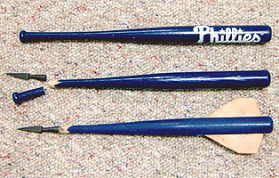
The third type of ammunition used with the catapulta are these smaller, but nasty "Dura-Europos" style arrow darts. They are based on historical references and typical of what these engines actually utilized as "shield-piercers". Legion XXIV's darts were made using 18 inch long mini-bats sold at ballpark stores, as shown at RIGHT. The handle knob was cut-off and a standard pyramidal arrow point applied. Larger points that better fit the shaft have been commissioned, as the socket of the standard arrow points used here are too small to fit securely over the thicker shaft of the mini-bat dart. Leather fletching helps the 11 ounce dart fly a more true coarse. A notch is cut into the heel of the dart to provide a better fetch for the casting sling. Credit Greg Fabic, Severus Tascius Fabius of Legion XX for the "mini-bat" idea.
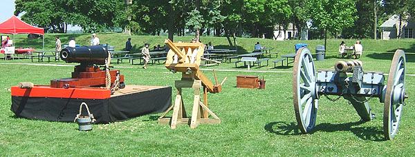
The Legion XXIV Catapulta flanked by a "Caronade" ships gun and a wheeled Six Pounder Field Piece at Fort Malden in Amherstburg, Ontario. The Caronade was a shorter and lighter type of cannon which permitted warships to carry more guns. One can only imagine what Roman history could have been if the Legions had had weapons like these? Note the sponge rod, "worm" rod and water bucket near the caronade and the powder boxes behind the catapulta.
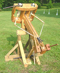
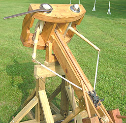
The upgraded "Scorpion of Terror" Cocked and Ready for Discharging. Note how the arms are pulled back against the torsion power of the twisted rope skeins. Note the iron spanner wrench in place on the left hand "modiolus" collar. The wrench is used to twist and impart torsion power into the skeins. One engine of this or smaller size was usually assigned to most of the 59 Centuries of a Legion.
See below for more on the construction and enhancements to the Engine of Terror.
8888888888888888888888888888888888888888888888888888888888888888888888888888888888888888
*** S.P.Q.R. *** LEGION XXIV MEDIA ATLANTICA *** S.P.Q.R. ***
DETAILS - ENHANCEMENTS - ASSEMBLY OF LEGION XXIV'S CATAPULTA
During March and May 2005 the catapulta was upgraded with a period correct trigger and the proper skein bundle collar-washers (modiolus) and anchor bars (epizygis). New skein bundles were put in place and tensioned rendering the engine about 30% stronger than before. To handle the increased tension and power, a double rope and pulley system was installed to reduce by half the force needed at the windlass (carchesium) for drawing back the slider (chelonium) and cross arms (bracchium) which cocks the engine for the launching of arrow bolts.
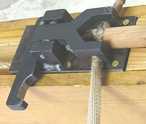
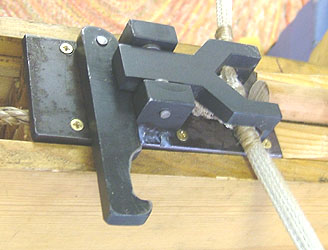
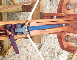
A new period accurate trigger was installed in March 2005. Above - The trigger claw is shown engaged over the catapult sling with an arrow bolt positioned between the forks of the claw and resting against the sling engaged behind the claw forks. The trigger claw is locked in the engaged position with its tail portion pressing down on the pivoting trigger release bar. Below - The release bar has been pulled to the rear and out from under the tail portion of the trigger claw, allowing the tail of the claw to slip off the release bar and pivot downward, allowing the sling to pull out from under the forks of the claw and launch the arrow bolt. The brass hex-head screws were later camouflaged after successful field trials.
================================================================================
MODIOLUS and EPIZYGIS UPGRADES

ABOVE LEFT - The various components of the skein Modiolus collar, Epizygis bars, locking pins and spanner wrench for torsioning the skein bundles. At Top Left, the collar set components are shown separated top-side-up. Top Right, shows the same components inverted, as they will be when installed on the bottom side of the skein head frame (capitulo). At Bottom Left the collar set is assembled and inverted with a locking pin in place. Bottom Right shows the collar set assembled and top side up. The spanner wrench slides over and engages the ends of the "epizygis" skein anchor bar to turn the "modiolus" collar and thereby tension the skeins. ABOVE RIGHT - The bottom side of the skein head frame is shown with the old skein bundle at the left and the new collar components at the empty skein bundle hole on the right. The brass under-washer is positioned and secured around the hole. The collar will be placed over the brass washer with its lower flange through the washer and it will then rotate on the washer as the collar is turned to torsion the skeins to provide the launching power for the engine.
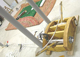
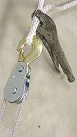
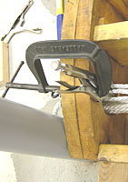
An ideal arrangement was available for tensioning the plies of the skeins. Two columns about 30 inches apart to brace the head frame against, and a third column about 5 feet away for attaching the "come-along" hand cable puller for pulling and building tension in each skein ply as it was threaded through the frame and collars. Two sets of vice-grip locking pliers and a large C-clamp were used to hold the built-up tension as the next skein ply was threaded into place, as shown above. A vise-grip was used to lock the rope loop at the cable puller and a second vice-grip, held in place by a C-clamp, holds the built-up tension so that the cable puller can be released for the threading of the next skein ply.
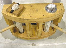
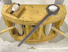
The head frame showing the twisted and torsioned old skein at left and the new tensioned, but not-torsioned or not-twisted skein at right. The old skeins had 18 plies of 3/8 inch diameter nylon rope, while the new skeins are composed of 16 plies of 7/16 inch nylon rope. The spanner wrench is shown in position for torsioning or twisting the skeins. The Romans used horse hair, sinew, hemp and gut to fabricate their catapulta skeins, but due to a modern lack of horse hair rope and a short supply of neighborhood cats for gut, we had to cheat and use nylon rope which has characteristics similar to the ancient skein materials.
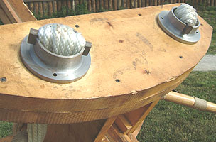
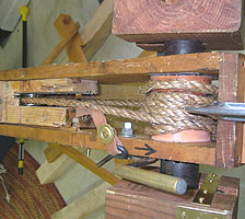
Close-up view of the "modiolus" collars with 16 plies of 7/8 inch nylon rope passing over the "epizygis" skein anchor bars. AT RIGHT - To handle the increased tension and power of the skeins, a double rope pulley system was installed to reduce by half the force needed at the windlass (carchesium) for drawing back the slider (chelonium) and cross arms (bracchium) which cocks the engine for the launching of arrow bolts. The pulley is visible at the left buried within the slider. It is anchored by a horizontal steel bar through the slider beam. The "safety" pin, which is inserted behind the trigger release during the "cocking" operation, and its retaining strap is shown, with the handle of the windlass locking pawl just below it.
================================================================================================
RATCHET WINDLASS UPGRADE
The original windlass system was descended from a SCA hand crank winder, which was not historically correct. It did the job, but at times, was clumsy and inefficient, despite several attempts to correct its short-comings. During early 2006, a whole new ratcheting windlass assembly was engineered and fabricated by the Commander and installed within a new tail-box. This major enhancement completes the upgrade of the catapulta to near historical accuracy and appearance.
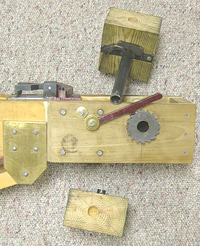
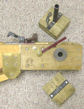
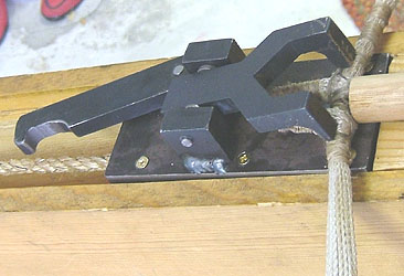
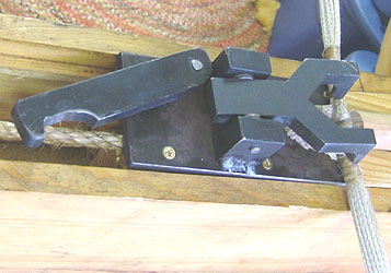
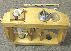
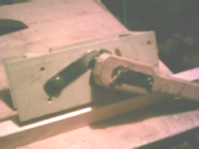
Two views of the new windlass components. The new windlass consists of two cog gears, one on each side of the tail-box, affixed to a 3/4 inch diameter hollow shaft. The winder blocks are fastened to the ends of a 1/2 inch diameter shaft, which passes through and rotates within the 3/4 inch cog-gear shaft. In the LEFT view, the claw trigger is closed and locked, as it would be over the sling rope when the engine is being wound and cocked. The tension retaining pawl is shown engaged on the cog-gear and ratchet pawl is in the cog-gear engaging position on the upper winder block. The lower winder block will be affixed and pinned into the end of the shaft upon final assembly. In the RIGHT view, the claw trigger is open, as after the sling rope is released to discharge the engine. The tension retaining pawl is disengaged from its cog-gear and the ratchet pawl is shown in the its disengaged position on the upper winder block, as they will be to allow the windlass to "free-wheel" when the slider is repositioned forward for the next shot. An additional lobe piece was added to the ratcheting pawl on the upper block to provide extra weight for a more positive engagement into its cog-gear.
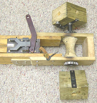
View showing the claw trigger and new windlass box with the 1/2 inch diameter winder block shaft partially inserted into the 3/4 inch diameter spool shaft. The winding pawl is shown flipped forward to slip over and engage its cog-gear.
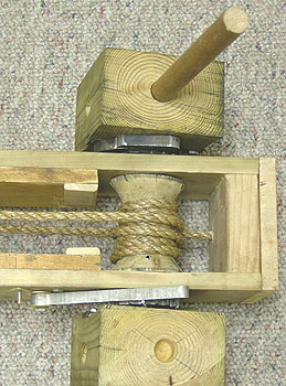
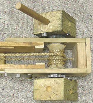
Down-on views of the assembled windlass. LEFT - The ratchet pawl (top) and tension retaining pawl (lower) are shown in their engaged "winding" positions on their respective cog-gears. Note the roll-pin in the lower cog-gear, which secures it to its shaft, permitting it to be removed should disassembly of the windlass be required. RIGHT - The two pawls are seen disengaged from their cog-gears to permit the windlass spool to "free-wheel" and unwind when repositioning the slider rail forward for the next cranking and cocking of the weapon. The winding rope is fastened to the spool using a stud into one of the two pins which secures the spool to the shaft, one of which is visible just below the wound rope. The other end of the rope passes below the spool and is "dead-ended" through the back end of the box and knotted. The knotted end will be covered with an additional block with a cavity to hide the knot.
8888888888888888888888888888888888888888888888888888888888888888888888888888888888888888
ASSEMBLY AND SET-UP OF THE CATAPULTA
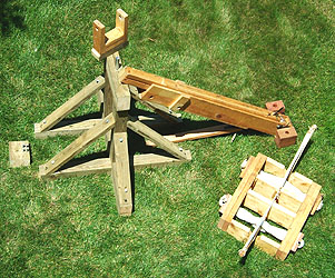
A sequence of views showing the stages and method of assembling the Catapult for use.
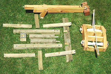

Left, The Legion XXIV Catapulta is shown disassembled into its component parts for transport. The slider and channel tail beam assembly is at top with the torsion head at the right. The large vertical 4 x 6 inch timber, lying on its side, is notched to fit over the longer 4 x 4 horizontal base pieces, to the left, which form the feet of the support stand. The 4 x 4 pedestal uprights, between the foot beams, are doweled to fit into the top of the foot beams. The other smaller 2 x 4 pieces are used to brace the stand. The square block at left is drilled to hold the 12 securing spikes, plus 4 spares. - Right, The foot beams with one of the pedestal uprights and braces are in place. Two of the securing spikes are shown extending from their holes. The 4 x 6 upper bearing block (missing from the first view) with two mounting dowels and 1 inch diameter iron pipe pivot is shown near the torsion head.
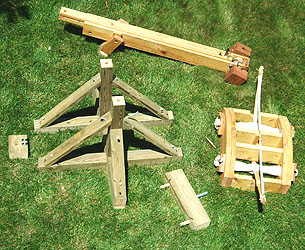
Left, The base, pedestal uprights and braces are in place. Note the holes in the top of the pedestals into which the two wood dowels of the bearing block will fit. Only the four spare spikes remain in the storage block at left. - Right, The slider beam assembly is resting on the bearing block. The mounting yoke for the slider beam sits on the bearing block. The yoke was retrofitted with a 1 1/4 inch pipe that slips over the 1 inch pivot pipe on the bearing block to provide a tighter and more wear-resistant pivot point.
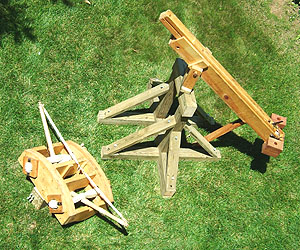
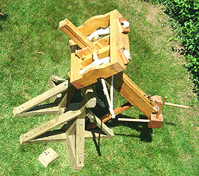
Left, The slider and channel beam assembly has been mounted on the base stand. The torsion head sits ready to be mounted over the end of the slider beam. Note the pivoted prop which supports the back end of the slider beam and is also used to set the elevation angle. Right, The fully assembled scorpion-catapult stands ready for use with the torsion head mounted on the forward end of the slider beam.
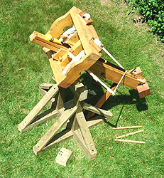
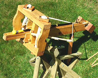
The "Engine" cocked and ready to discharge. UUH - RAAA !! Carry On !
=============================================================================
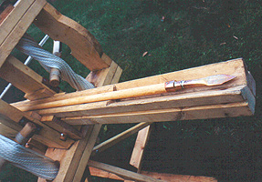
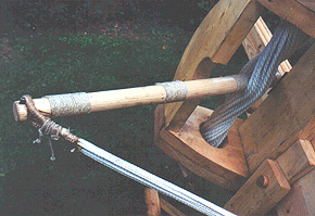
An arrow-bolt resting in the slider trough. The left-hand torsion arm and torsion bundle.
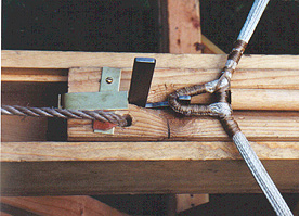
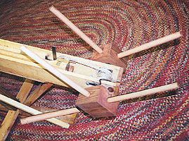
At Left, The casting sling loop is shown engaged on the original trigger pawl, with the trigger release lever holding the trigger pawl in place and with the butt of the arrow-bolt resting against the sling. A brass safety spring holds the trigger lever in the "engaged" position. A rope leads off to the cocking windless, out of view to the left. The trigger lever is pulled to the left to dis-engage the trigger pawl and release the tensioned sling to launch the arrow-bolt toward the right. At Right, The square cocking windless (carchesium) winch blocks with holes for insertion of removable levers (scutala) is shown at the tail end of the slider beam. Note the cocking pawl just above the lower winch block, which engages holes cut into the windlass shaft. This windless or winch arrangement replaces the original handled cranks, which were not historically correct, as this machine had been made for SCA battle use. The SCA or Society for Creative Anachronism is not as concerned with historical accuracy.
Ballista Page *** Trebuchet Page *** Home Page
Randi ratchet windlass Leg-III Oct-2008